Product
ДйПУЦвХв СІЧАРЛ МвАГЧеДЯДй.
CT/MRI
| СІИё | Catphan 700, Quality Control in Radiography / Fluoroscopy |
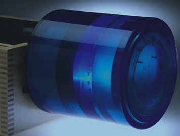
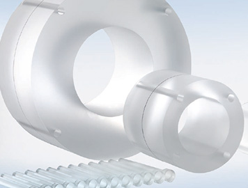
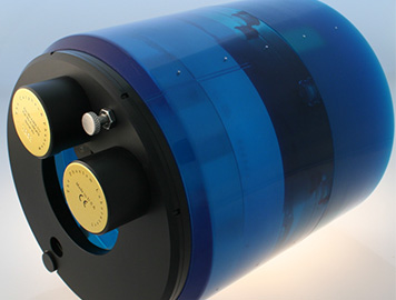  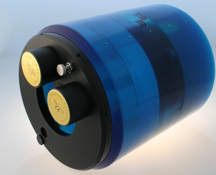 CatphanЂч 700 The CatphanЂч 700 Phantom has been designed to address the image performance measurement requirements for state of the art CT volume scanners. David Goodenough, Ph.D. utilized his 35 years of CT image quality research and testing experience to guide us through the research and development of the CatphanЂч 700. The phantom retains many of the tests and features offered in the other CatphanЂч models including the CTP515 low contrast test module and integrated case mounting system. Other test objects have been refined in this development including the addition of higher resolution test patterns in the new CTP714 1 to 30 line pair per centimeter test module, the addition of smaller acrylic spheres to our low contrast sphere array contained in the CTP682 sensitometry slice geometry module, and additional bone and lung samples to assist customers using their CT images for radiation therapy treatment planning. Along with numerous modifications, the phantom also contains the new CTP721 wave insert for measuring slice geometry and resolution across the scan area. Also, in order to address possible variables due to test pattern orientation with the scanners x and y axis, the phantom has a new rotation mount. This enables the mounted phantom to be rotated 360ЁЦ with alignment detents at 45ЁЦ intervals to study possible angular position-dependent results. 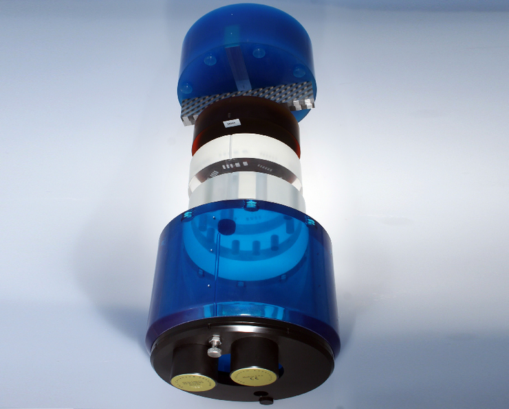 CatphanЂч 700 design and construction Test precision, durability, and efficient operation are the key design. The CatphanЂч 700 continues to utilize the modular concept developed with the original CatphanЂч phantom. The three solid cast test modules are mounted inside the phantomЁЏs housing. The wave insert and complementary MTF bead blocks press into pockets on the uniformity body that attaches to the module housing. The new rotating mount is connected to the module housing. Using the new mount, the phantom can be quickly cantilevered off the end of the table and rotated into various angular positions to allow for artifact free scanning. While most customers will never choose to disassemble their phantom, special care was taken in the development of the CatphanЂч to enable disassembly for potential upgrades or modifications. To prevent hardware artifacts, no metal hardware is used to connect the wave uniformity section to the module housing or between the housing and the mount. 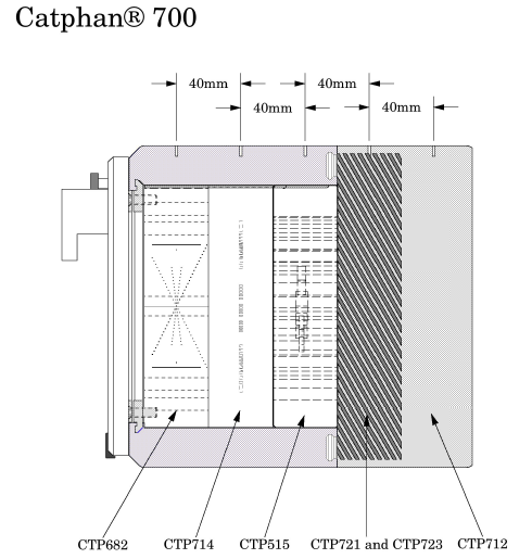 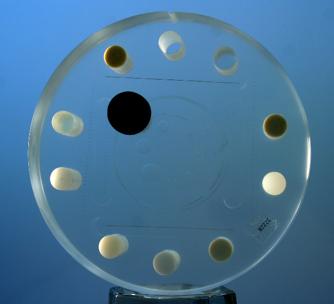 CTP682 Geometry Sensitometry Module The CTP682 module contains three sets of opposed slice geometry ramps. One of the ramp sets uses .15mm steel wires set at 23ЁЦ ramp angles to produce ramp images with a 2.4 magnification to reduce the effects of limited image measurements. Additionally, the small diameter wires reduce over-range streaking artifacts. The other two ramp sets are made from tungsten carbide beads. The coarse ramp with a z axis height of 38mm uses 0.28mm beads set in 1mm z axis increments and the fine ramps use 0.18mm beads set at .25mm z axis increments. The opposing pairs of ramps allow operators to easily verify whether the phantom is correctly aligned with the scanner axis. By measuring the ratio between opposed ramps, gantry angles up to 10ЁЦ can be verified, avoiding erroneous measurements. For sensitometry measurements, this module has 10 samples and a water container. The materials include Teflon, 50% Hydroxyapatite, Delrin, Acrylic, Polystryene, LDPE, PMP, and Air. Pixel size can be calculated by counting the number of pixels between the four precisely machined test cylinders, which form a square in the x and y directions. The module also contains eight acrylic spheres to evaluate the scannerЁЏs imaging of subslice spherical volumes. The diameters of the acrylic spheres are 1mm, 1.5mm, 2mm, 3mm, 4mm, 6mm, 8mm, and 10mm. For detailed MTF and SSP calculations, two isolated beads 0.28mm and .18mm in diameter are located in the mid plane of the module. For thin slice high-resolution measurements, a 50Ѕь diameter steel MTF wire runs through the full 40mm thickness of the module.  CTP714 30 Line Pair High Resolution Module The unique design of the CTP714 minimizes visual artifacts by reducing the amount of high contrast material. The 2mm thick aluminum contrast figures are cast into position on the radial octagonal pattern, which has resolution sections ranging from 1 to 30 line pairs per cm. This resolution gauge pattern greatly reduces the possibility of streaking artifacts from other test objects. The combination of the octagonal design and the rotating mount with 45ЁЦ indices enables all gauge segments to be measured either aligned with the x or y axis, or at a 45ЁЦor 90ЁЦ angle.  CTP515 Low Contrast Module The CTP515 consists of a series of cylindrical rods of various diameters and three contrast levels to measure low contrast performance. The 40mm-long rods provide consistent contrast values at all z-axis positions, thereby avoiding any volume-averaging errors as one scans through the section. In addition, the unique subslice test objects enable evaluation of the effectiveness of different scan protocols (pitch, slice width, and reconstruction algorithms) in resolving subslice low contrast objects. For selection of helical and multi-slice image protocols, unique subslice low contrast targets (truncated cylinders) have been included in this module. Comparing the images obtained by scanning the subslice targets with different imaging settings (slice width, pitch, and reconstruction algorithms) provides valuable information to assist with the selection of optimal protocols for identifying small low contrast objects such as tumors. All of the various samples and the background material have equivalent effective atomic numbers; only the density is varied to produce changes in the effective attenuation coefficients. Subslice targets have a nominal 1.0% contrast and z-axis lengths of 3, 5, and 7mm. For each of these lengths, there are targets of 3, 5, 7, and 9mm 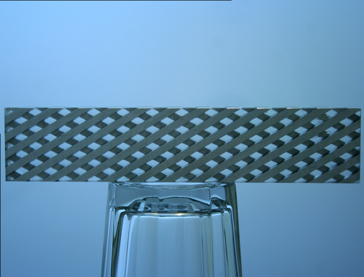 CTP721 Wave Insert and CTP723 Bead Blocks Located at the top of the CTP712 Uniformity Section are three pockets that hold the CTP721 Wave Insert and 2 CTP723 Bead Blocks. The Wave Insert has repeating 4mm thick ramps alternating between aluminum and clear urethane rising at 30ЁЦ angles from the slice plane. The inset contains two opposed alternating ramp sets. CT images of the Wave Insert have an alternating dark and light pattern resulting from the ramps. When a profile is made across the alternating pattern the resulting plot will reveal a cross between a square and triangle wave. The actual wave pattern is influenced both by slice thickness and scanner resolution. By analyzing the pattern along with MTF measurements from the Bead Blocks, slice width and/or high resolution variations across the slice can be identified. Additionally, the side view honeycomb-like pattern provides a test pattern for visual or analytic assessment of 3-D consistency. 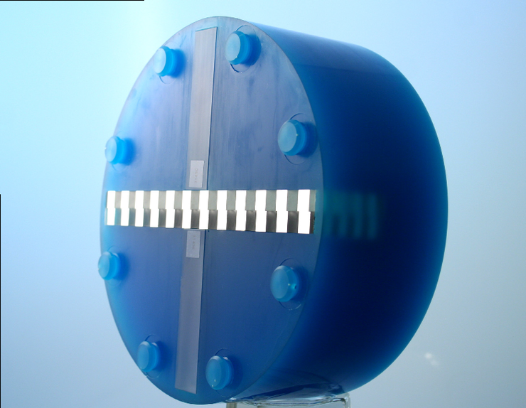 CTP712 Uniformity Section The CTP712 solid-image uniformity section provides consistent results, and is much more convenient than water-filled tanks, eliminating variations due to different water sources. Additionally, the Uniformity Material is extremely durable. The CatphanЂч Uniformity Material has a CT number within 2% (0-20H) of water. This solid materialЁЏs high radial and axial uniformity makes it an ideal substitute for water. It has been thoroughly tested over a wide variety of variables in the x, y, and z planes and has proven stable in all applications. |
|
| ФЋХзАэИЎ | |
| ЙЎРЧЧЯБт |


|

|