Product
ДйПУЦвХв СІЧАРЛ МвАГЧеДЯДй.
CT/MRI
| СІИё | Pro-CT MINI, CT phantom, IEC 61223-3-5, AAPM |
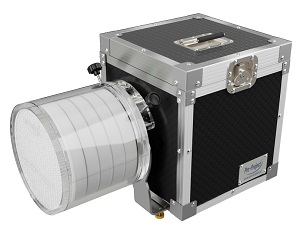
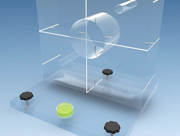
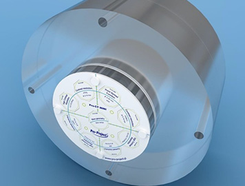 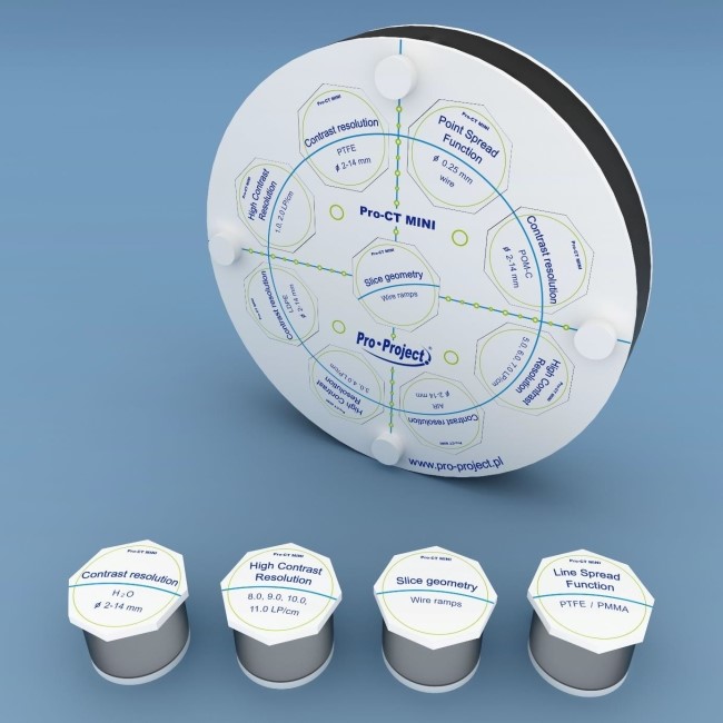 Pro-CT MINI The Pro-CT MINI phantom is a compact CT image quality testing solution. When connected with Pro-CT Dose it may be used for carrying out acceptance and constancy tests of computed tomography systems according to IEC 61223-3-5 and the AAPM (American Association of Physicists in Medicine) guidelines. This phantom consists of a module 16cm in diameter with positioning aids and recesses for test modules. 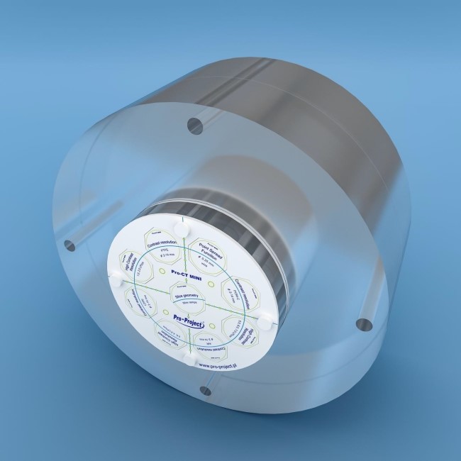 For correct operation, appropriate total attenuation, phantom must be attached to the Pro-CT Dose M phantom using screws and dedicated plugs as shown below. Defending on attenuation needed you may use only Pro-CT Dose M or Pro-CT Dose L as well. Phantom houses 9 test inserts. You can choose which ones to use and in what combination. Each test insert has a unique pattern on its base that is used by the auto-analysis system – Pro-Control.online to automatically identify which module is where. • Position the phantoms in the CT scanner and scan the test phantom. • Analyze image. • If necessary repeat the procedure with a different setup of test inserts. 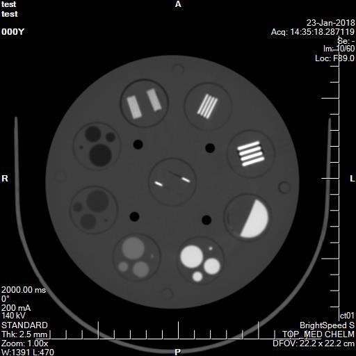 Spatial resolution • evaluate the number of distinguishable high contrast patterns Recommendations: • number of distinguishable high contrast objects should not differ from reference values. HU values • measure a mean value of HU in ROIs (Region Of Interest) placed in centre of each sensitometric sample and body of the module Recommendations: • difference in mean HU values for each sensitometric sample and module body should be constant in time – differ less than ЁО 4 HU from reference values. Low contrast resolution • evaluate the number of distinguishable low contrast objects in each module Recommendations: • number of distinguishable low contrast objects in each group should not differ from reference values. FWHM measurement (Geometry, ramps) To calculate FWHM (Full Width at Half Maximum) for wire ramps maximal HU values for background and ramps must be evaluated. To find the ramp maximum restrict the window to 1 or lowest selectable value. Move the window centre to the point when ramp image almost disappears. This level value is maximum for the ramp. Background can be evaluated using ROI tool – mean value of HU near ramps. Net HU peak = maximal HU value for ramps – background Half peak net = Net HU peak / 2 HU Value at half maximum = Half peak net + background • set window centre to calculated HU value and window width to 1 • measure ramp length to get FWHM Image geometry • measure distances between four rods in horizontal, vertical and diagonal directions. Rods are placed in vertexes of square 45x45mm rotated. • Additionally there is a set of holes in vertical and horizontal direction with 5mm spacing running across two axis of the phantom near the outside surface Recommendations: • dimensions measured on the image shouldnЁЏt differ from actual values more than ЁО1mm 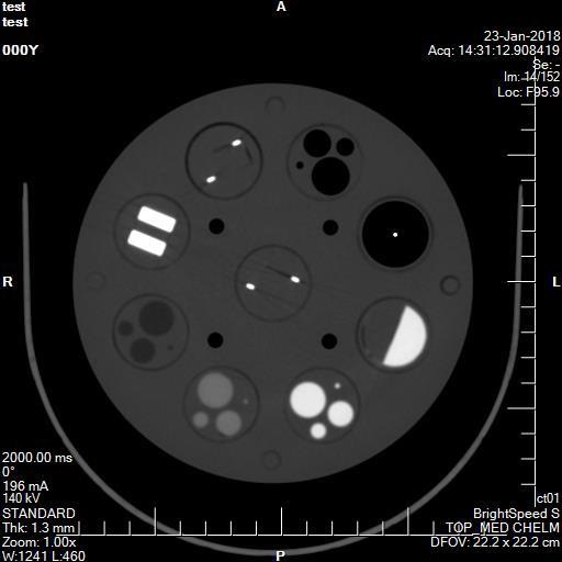 Slice thickness • measure length of ramp images using FWHM procedure. Length of the ramp is equal to the slice thickness Recommendations: • measured slice thickness should not differ more than ЁО20% form actually set value. Alignment • mark main axes of the insert • measure distances between middles of ramp images and inser axes to get actual position of slice. Recommendations: • measured distance should not be greater than 2mm Noise level • measure a standard deviation of HU in 500mm2 ROI (Region Of Interest) near the centre of the Pro-CT Dose – next to the central plug Recommendations: • standard deviation in ROI shouldnЁЏt differ more than ЁО 20% from reference values. Homogeneity • measure a mean value of HU in 500mm2 ROIs (Region Of Interest): in centre of the Pro-CT Dose phantom and in four places near its border. Place ROI next to the plugs, not on them. Recommendations: • difference in HU value between the centre and sides should be constant in time – differ less than ЁО 4 HU from reference values Technical data (can be modified to customer specifications): • main module: –– diameter: 160mm –– thickness: 30mm –– 9 recesses for test inserts allow the customized placement of test objects in space –– markings for easy and accurate positioning in the CT scanner –– set of holes on a given depth for testing geometry, distortions and slice position. –– screws and extra plugs for mounting the module on any Pro-CT Dose phantom • standard test inserts –– 5 contrast resolution inserts containing rods made from different materials: LDPE, PTFE, POM-C, air, plastic water equivalent. Diameters of rods in each insert are: 2, 4, 6, 8, 10, 12, 14mm –– 4 high contrast resolution inserts containing 11 aluminium test elements for spatial resolution evaluation from 1 to 11 LP/cm –– 2 geometry modules containing two pairs of aluminium wire ramps whose slope angle tangent is equal to 0.5. –– Linear Spread Function (LSF) insert - PTFE / PMMA interface –– Point Spread Function (PSF) insert - 0.25 mm tungsten steel wire in air • optional inserts (04-404) –– 3 low contrast inserts containing rods with a diameter: 2, 4, 6, 8, 10, 12, 14mm. The contrast difference between the rods and the surrounding material are 0.3, 0.6 and 1%. –– 3 high contrast resolution inserts containing 19 aluminium test elements for spatial resolution evaluation from 12 to 30 LP/cm • Carrying case Product features: • complies with: –– IEC 61223-3-5 –– IEC 61223-2-6 –– AAPM guidelines • CE certified • the Manual provides detailed guidelines for carrying out each test, results assessment and registration |
|
| ФЋХзАэИЎ | |
| ЙЎРЧЧЯБт |


|

|