Product
ДйПУЦвХв СІЧАРЛ МвАГЧеДЯДй.
CT/MRI
| СІИё | Quality Control in Radiography / Fluoroscopy |
   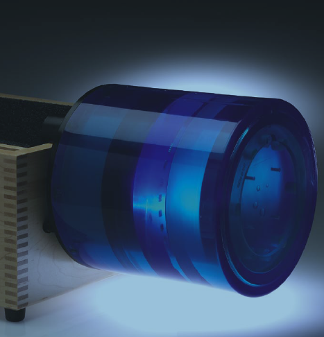 CatphanЂч 500 Designed to evaluate the maximum performance potential of axial and spiral CT scanners.  CatphanЂч 500 test module locations: Module Distance from section 1 center CTP401 CTP528, 21 line pair high resolution 30mm CTP528. Point source 40mm CTP515, Subslice and supra-slice low contrast 70mm CTP486, Solid image uniformity module 110mm CTP401 Module with slice width, sensitometry and pixel size (Teflon, Acrylic, LDPE, Air) 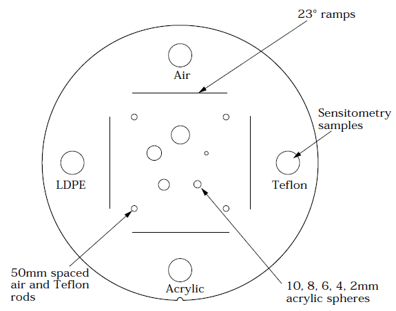 CTP401/404 Slice Geometry and Sensitometry Module Diameter: 15cm Thickness: 25mm • scan slice geometry (slice width) • circular symmetry • phantom position verification • sensitometry (CT number linearity) • patient alignment system check • pixel (matrix) size • scan incrementation The CTP401 test module in the CatphanЂч 500 includes sensitometry samples for Teflon, Acrylic, LDPE and Air. The CTP404 test module used in the CatphanЂч 600 includes sensitometry samples for Teflon, Delrin, Acrylic, Polystryene, LDPE, PMP, Air and a small vial for water. Pixel size can be calculated by counting the number of pixels between the test cylinders in the x and y directions. The module also contains five acrylic spheres to evaluate the scannerЁЏs imaging of subslice spherical volumes. The diameters of the acrylic spheres are 2mm, 4mm, 6mm, 8mm, and 10mm. CTP528 High resolution module with 21 line pair per cm gauge and point source 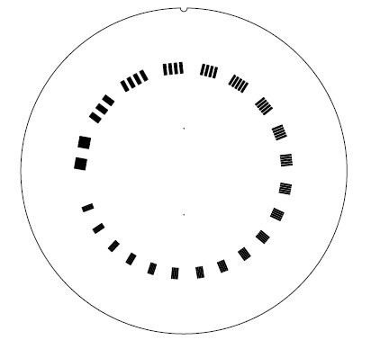 CTP528 High Resolution Module Diameter: 15cm Thickness: 40mm • scan slice geometry (slice width and slice sensitivity profile) • high resolution (1 to 21 line pairs per cm) • point spread function and modulation transfer function (MTF) for the x, y, and z axes The unique design of the CTP528 minimizes visual artifacts by reducing the amount of high contrast material. The 2mm thick aluminum contrast figures are cast into position on the radial gauge, which has resolution sections ranging from 1 to 21 lines pairs per cm. This radial design pattern eliminates the possibility of streaking artifacts from other test objects. This section, combined with spherical beads – rather than wire – for MTF measurements, allows operators to avoid the tedious and time-consuming step of positioning and aligning MTF wires with the z axis. The point source beads also eliminate the over-ranging problems and streaking artifacts that occur with MTF wires, because the bead density is volume averaged with the surrounding material CTP515 low contrast module with supra-slice and subslice contrast targets  CTP515 Low Contrast Module Diameter: 15cm Thickness: 40mm • low contrast sensitivity • comparative subslice and supra-slice low contrast sensitivity The CTP515 consists of a series of cylindrical rods of various diameters and three contrast levels to measure low contrast performance. The 40mm-long rods provide consistent contrast values at all z-axis positions, thereby avoiding any volume-averaging errors as you scan through the section. The unique subslice test objects enable evaluation of the effectiveness of different scan protocols (pitch, slice width and reconstruction algorhythms) in resolving subslice low contrast objects. For selection of helical and multi-slice image protocols, unique subslice low contrast targets (truncated cylinders) have been included in this module. Comparing the images obtained by scanning the subslice targets with different imaging settings (slice width, pitch and reconstruction algorithms) provides valuable information to assist with the selection of optimal protocols for identifying small low contrast objects such as tumors. All of the various samples and the background material have equivalent effective atomic numbers; only the density is varied to produce changes in the effective attenuation coefficients. Subslice targets have a nominal 1.0% contrast and z-axis lengths of 3, 5, and 7mm. For each of these lengths, there are targets with diameters of 3, 5, 7 and 9mm. CTP486 Image uniformity module  CTP486 Uniformity Module Diameter: 15cm Thickness: >40mm • spacial uniformity (noise) • noise (precision) of CT systems The CTP486 does not leak and is not damaged by exposure to freezing temperatures because it does not use water. While water is generally considered the standard calibration material, many physicists prefer using our CTP486 solid-image uniformity module because it provides consistent results, is much more convenient to use than modules using water-filled tanks, and eliminates variations due to different water sources. The CTP486 module is cast from a uniform material that has a CT number within 2% (0-20H) of water. This solid materialЁЏs high radial and axial uniformity makes it an ideal substitute for water. It has been thoroughly tested over a wide variety of variables in the x, y and z planes and has proven stable in all applications. |
|
| ФЋХзАэИЎ | |
| ЙЎРЧЧЯБт |


|

|